


What Is a Die Casting Mould?
A die casting die (spelled die casting mold in American English) is a precision-engineered tool used in the die casting process—a manufacturing technique for producing metal components by injecting molten metal into a mould cavity under high pressure.
These tools are critical for high-volume production, particularly in the automotive, electronics, and industrial sectors. Commonly used with aluminium, magnesium, and zinc alloys, the die cast mould is designed to endure extreme temperatures and pressures. Their robust construction allows for the rapid and accurate injection of molten metal into precisely shaped cavities, ensuring the consistent production of complex, high-quality parts.
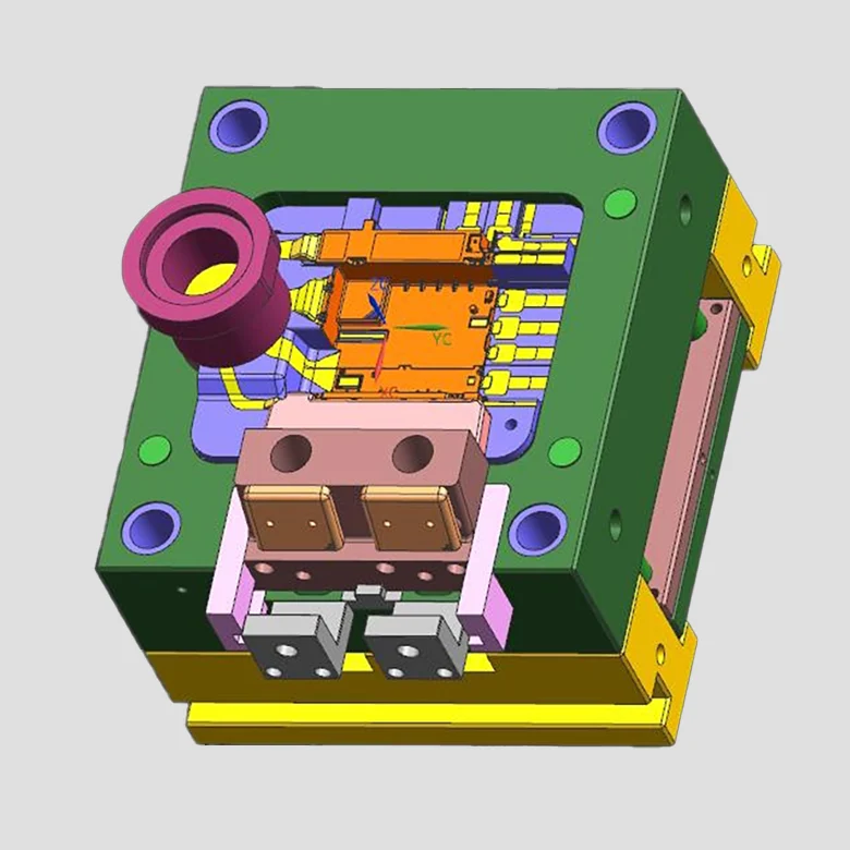
1. Definition and Structure of Die Casting Moulds
- Stationary half (cover die)
- Moving half (ejector die)
During the die casting cycle, molten metal is injected into the cavity formed between these two halves. Once the metal solidifies, the moving half opens, and ejector pins push the finished casting out of the mould. A release agent (lubricant) is then sprayed onto the cavity surfaces to facilitate smooth ejection and prepare the mould for the next shot.
Key Structural Components of a Die Casting Tool:
- Moulding System
Forms the final shape of the casting using cavities, cores, sliders, and inserts. - Mould Base
Provides structural support and alignment. It includes base plates, support blocks, and fastening elements. - Ejection System
Responsible for ejecting the solidified casting, typically using ejector pins, return pins, and guide systems. - Runner System
Channels the molten metal from the injection unit into the cavity with precision and minimal turbulence. - Overflow and Venting System
Facilitates the escape of air and excess metal during filling, helping to avoid defects such as porosity and incomplete filling. - Additional Components
Includes guide pillars, locating rings, clamping elements, and cooling channels to ensure mould alignment, stability, and thermal regulation.
2. Die Casting Process Overview
High-Pressure Die Casting (HPDC) is a precise and efficient manufacturing process used to produce complex metal components with tight tolerances and high-quality surface finishes. The process involves injecting molten metal into a steel mould cavity at extremely high speeds (up to 70 m/s) and under pressures of up to tens of megapascals (MPa).
The choice of die casting machine depends on the type of metal alloy being used:
- Cold Chamber Die Casting – Typically used for aluminium, magnesium, and copper alloys.
- Hot Chamber Die Casting – Preferred for low-melting-point metals such as zinc.
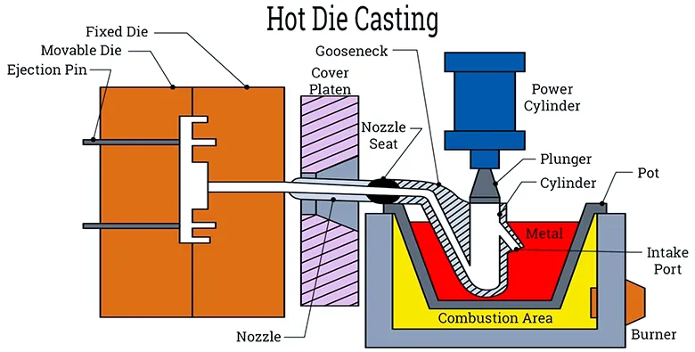
Key Stages of the Die Casting Process
- Mould Clamping
The two halves of the die (stationary and moving) are clamped together securely to resist the high injection forces. - Metal Injection
Molten metal is rapidly injected into the cavity through a gating system, ensuring full and even cavity fill. - Cooling and Solidification
The molten metal cools and solidifies under constant pressure, maintaining part integrity and dimensional accuracy. - Part Ejection
Once solidified, the die opens and ejector pins push the casting out of the mould. - Mould Lubrication
A release agent is sprayed onto the die cavity to aid ejection and prepare the mould for the next shot. - Cycle Repeats
The process restarts rapidly for high-volume, consistent part production.
3. Key Considerations in Mould Design
The success of the die casting process relies heavily on the precision and suitability of the mould design. A well-engineered mould ensures optimal flow of molten metal, efficient cooling, and defect-free part ejection. Key considerations during the design and development phase include:
- Material Selection
Choose mould materials that offer high wear resistance, thermal stability, and strength to endure cyclic thermal loading and high-pressure injection. - Draft Angles and Parting Lines
Incorporate adequate draft angles to facilitate part ejection and define clean, strategically located parting lines to simplify tooling and reduce flash. - Wall Thickness and Structural Features
Ensure uniform wall thickness wherever possible to promote consistent filling and solidification. The inclusion of fillets, ribs, and bosses should be optimised to reduce stress concentration and improve material flow. - Undercuts and Moving Components
Account for any undercuts early in the design phase. Slides, lifters, or collapsible cores may be required to release complex features without damaging the part or mould. - Ejection System Design
Plan ejection mechanisms carefully, considering pin placement, stroke, and the risk of distortion or marking on critical surfaces. - Venting and Overflow Channels
Integrate vents and overflow systems to allow trapped air and excess molten metal to escape, preventing porosity, cold shuts, and incomplete fills. - Post-Processing Requirements
Anticipate machining, finishing, or coating operations during mould design to ensure sufficient allowances and tolerances are included.
A thorough evaluation of these elements helps ensure the mould performs reliably over its intended lifespan, delivering consistent, high-quality parts with minimal downtime or defects.
4. Mould Manufacturing Process
The manufacturing of a die casting mould is a highly precise, multi-stage process involving advanced machining techniques and rigorous quality control. Each step plays a critical role in ensuring the mould meets the stringent requirements for dimensional accuracy, surface finish, and long-term durability under high-pressure conditions.
Key stages of the mould manufacturing process include:
- CNC Machining
High-precision computer-controlled milling and turning operations are used to shape the mould base and core components according to 3D CAD models. - Electrical Discharge Machining (EDM)
EDM is employed to produce intricate features, deep cavities, and sharp corners that cannot be achieved by conventional machining. - Grinding and Polishing
Surfaces are ground to precise tolerances and then polished to achieve the smooth finish required for optimal metal flow and part release. - Heat Treatment and Stress Relief
Mould components are heat treated to enhance hardness and wear resistance. Stress relief procedures reduce internal stresses that could lead to deformation or cracking during operation. - Drilling and Tapping
Holes for cooling channels, ejector pins, and fasteners are carefully drilled and tapped to ensure alignment and proper assembly. - Assembly and Fitting
All mould components—including inserts, cores, sliders, and lifters—are assembled and fitted to ensure seamless operation under high-pressure casting cycles. - Surface Coating and Nitriding
Surface treatments such as nitriding or PVD coatings are applied to improve hardness, reduce friction, and extend the mould’s service life.
This rigorous production process ensures that every die casting mould delivers consistent performance, dimensional accuracy, and durability across repeated production cycles.
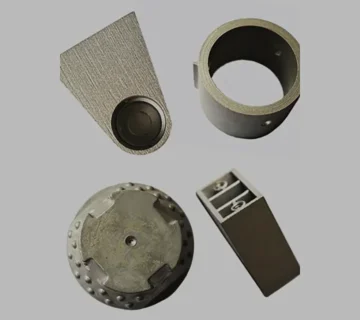
5. Types of Die Casting Moulds by Material
Die casting moulds are selected based on the specific metal alloy being cast, as each material requires moulds with tailored properties to ensure optimal performance and longevity.
Aluminium Alloy Moulds
- Melting Temperature: 650–700°C (1200–1290°F)
- Common Tool Steels: H13, H11, Y10, HM3
- Key Considerations: Moulds for aluminium alloys must resist thermal cracking and soldering caused by the high casting temperatures and reactive nature of aluminium.
Zinc Alloy Moulds
- Melting Temperature: Approximately 400°C (752–806°F)
- Common Tool Steels: 40Cr, 4Cr5MoSiV, 5CrNiMo
- Key Considerations: Zinc alloy moulds focus on surface durability and wear resistance due to the alloy’s relatively lower melting point but aggressive flow characteristics.
Magnesium Alloy Moulds
- Melting Temperature: Around 650°C (1202°F)
- Common Tool Steels: H13 (typically for cavities), medium to low carbon steels for other mould components
- Key Considerations: Emphasis is placed on cavity strength and dimensional stability to withstand the stresses and thermal cycling encountered during magnesium casting.
6. Mould Maintenance During Idle Periods
Effective storage and maintenance during periods of inactivity are crucial to prolong the service life of die casting moulds. Key practices include:
- Thorough Inspection: Carefully examine the mould for any signs of damage or wear before storage.
- Comprehensive Cleaning: Remove all residues, moisture, and oils to prevent corrosion and contamination.
- Surface Protection: Polish critical surfaces and apply appropriate rust inhibitors to safeguard against oxidation.
- Secure Storage: Use locking plates or clamps to keep mould components securely in place during storage.
- Controlled Environment: Store moulds in a clean, dry, and well-labelled area to facilitate easy identification and maintain optimal conditions.
7. Practical Design Guidelines
- Ensure Adequate Biscuit Size: Design the biscuit to facilitate proper molten metal flow and minimise defects.
- Machinery Compatibility: Align mould design with the specifications and capabilities of the available die casting machines.
- Post-Processing Considerations: Account for subsequent processes such as machining, coating, or surface finishing during the design phase.
- Temperature Control Integration: Incorporate effective mould temperature control systems to optimise cycle times and part quality.
- Handling and Safety: Design for safe lifting, balance, and ease of handling during mould installation and maintenance.
No comment