


The Importance of Die-Casting Dies
This comprehensive document explores the fundamental aspects of the die-casting process and die design, focusing on the analysis of die cast die structures. As a critical component of the pressure casting process, die casting dies play a key role in ensuring high-quality production, accounting for approximately 70% of the overall impact on final die-cast quality. This document provides detailed insights into the various structural components, classifications, and design considerations essential for effective die-casting operations.
As long as the die-casting mold features a well-designed gating system, proper mold structure, and precise manufacturing accuracy, it meets the conditions for effective pressure casting. A well-designed mold can compensate for any limitations of the die-casting machine and provide a broader range for adjusting process parameters.
Die Casting Mold Classification
Die-casting tooling is essential for creating high-quality, precision parts. The structure of die-casting tooling is determined by several factors, including the die-casting machine used, the design requirements of the die-cast part, and the production volume. Understanding the various classifications of die-cast tools is essential for selecting the appropriate tooling for specific die-casting applications. Die-casting dies are categorised primarily by their structural characteristics, addressing various casting challenges. These classifications include single-parting-line dies and multiple-parting-line dies, each designed for different levels of complexity in the die casting process. Furthermore, we can classify die-casting tools based on the core-pulling mechanisms they employ, which are crucial for producing parts with undercuts or internal features. Examples include side-action core-pulling dies, thread-unscrewing dies, and two-stage ejection dies.
Single Parting Line Die Cast Tools
Single-parting line die-cast tools are the simplest die-casting tooling, featuring a single parting surface between the fixed and movable halves. These tools are ideal for casting parts with simple geometries that can be easily ejected without requiring complex core-pulling mechanisms.
Multiple Parting Line Die Casting Moulds
Multiple-parting-line die-cast moulds are used to produce more intricate die-cast parts. These dies feature multiple parting surfaces, creating complex geometries that would be challenging or impossible with a single parting line. Multiple-parting-line die casting dies require advanced die casting design and manufacturing techniques, making them suitable for a wide range of applications.
Side-Action Core-Pulling Die Casting Dies
Side-action core-pulling die-casting dies incorporate hydraulic or mechanical systems to withdraw cores from the side of the die before ejection. These die-cast tools are essential for producing parts with undercuts or internal features, which are otherwise difficult to remove without causing damage. This design helps optimise the ejection process, ensuring smooth and efficient production.
Thread-Unscrewing Die-Cast Moulds
Thread-unscrewing die-casting tools specialise in creating parts with internal or external threads. Rotating mechanisms in these dies unscrew the threaded cores before part ejection. This advanced die-casting tooling solution is crucial for parts that require precision threading, such as automotive and industrial components.
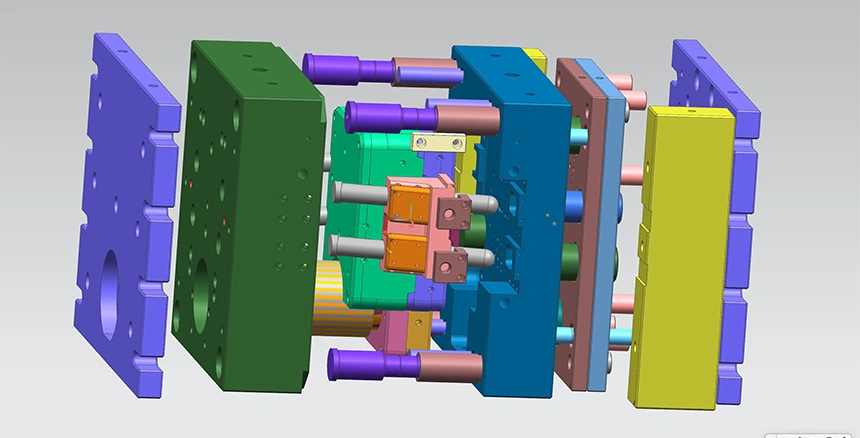
Basic Structure of Die Casting Molds
Die-casting molds consist of numerous components, each serving a specific function in the casting process. A thorough understanding of these components is essential for effective mold design and troubleshooting. Key components include fixed and movable mold halves, a gating system, a cooling system, an ejection system, and core-pulling mechanisms.
The fixed mould half (stationary die) remains attached to the die-casting machine’s stationary platen and typically contains the sprue through which molten metal enters the mould.
The movable mold half (ejector die) is attached to the moving platen and contains the ejection system, which pushes the solidified casting out of the mold after it opens.
Gating system: This system directs the flow of molten metal into the mold cavity, including components like sprues, runners, and gates.
Cooling system: it regulates the mould’s temperature, ensuring proper casting solidification.
The ejection system typically consists of ejector pins and plates, which remove the solidified casting from the mold.
Die Casting Components and Their Functions
| No. | Component Name | Description |
| 1 | Injection Plunger Rod | Connects the injection plunger to the injection piston rod, enabling the injection process. |
| 2 | Injection Plunger | Facilitates the transfer of molten metal into the mould cavity. Due to direct contact with the metal, it is subject to wear and requires regular replacement. Manufactured from materials such as cast iron, steel, or beryllium bronze. |
| 3 | Shot Chamber | Houses the molten metal, with an internal diameter that matches the injection plunger. It allows for injection and resetting actions. Constructed from heat-resistant steel. |
| 4 | Fixed Die Template | A component of the machine frame that supports the fixed mould and injection chamber. |
| 5 | Fixed Die Sleeve | The external frame of the fixed die, used to house and secure the fixed die insert and other components. It must be designed to withstand clamping and expansion forces, generally made from structural steel or ductile cast iron. |
| 6 | Gate Sleeve/Sprue Bush | Connects the injection chamber to the casting system, with an internal diameter matching the injection chamber. Typically made from durable steel. |
| 7 | Movable Die Insert | A component embedded in the movable die sleeve, which forms the mould cavity. It is also responsible for creating the gating system and overflow channels. Manufactured from high-quality heat-resistant steel. |
| 8 | Runner Cone | Directs molten metal into the horizontal runner of the gating system. Made of heat-resistant steel, it is subject to heat treatment for durability and is designed for easy replacement. |
| 9 | Ejection Pin | Ejects the die casting from the mould once the die is opened. Constructed from heat-resistant steel. |
| 10 | Movable Die Sleeve | The outer frame of the movable die, which secures the movable die insert, runner cone, and other components. Its structure is similar to that of the fixed die sleeve. |
| 11 | Ejection Limit Block | Restricts the ejection stroke to ensure safe and controlled ejection of the casting. |
| 12 | Support Block | Provides structural support for the movable die sleeve or die support block. Typically made from mild steel, structural steel, or cast iron, it must withstand clamping forces and be designed to accommodate deformation under pressure. |
| 13 | Movable Die Base Plate | Fixes the movable die to the machine’s movable platen, providing structural stability. |
| 14 | Die Platen | Provides the necessary structural support for the movable die and associated injection components. |
| 15 | Hydraulic Ejection Rod | Connects the push plate to the rear-end ejection cylinder, facilitating the ejection of the casting. This is part of the hydraulic ejection system. |
| 16 | Ejection Push Plate | Facilitates the ejection of the casting from the mould once it is fully formed. |
| 17 | Ejection Pin Fixing Rod | Secures the ejection pin to the push plate. Positioned at the parting line, it has a larger diameter and greater length than the ejection pin, and aids in resetting the push plate during mould closing. |
| 18 | Guide Sleeve Back Ring | Secures the guide sleeve in place, ensuring proper alignment and functioning. |
| 19 | Guide Sleeve | Works in conjunction with the guide pillar to ensure proper alignment and positioning of the mould during closing. Typically made from high-carbon steel or tool steel and installed in the movable die. |
| 20 | Guide Pillar | Works with the guide sleeve to ensure accurate alignment and positioning during mould closure. Made from high-carbon steel or tool steel, typically installed in the fixed die. |
| 21 | Movable Core | Used to form recessed areas on the side of the die casting, with the rear section connected to a hydraulic core puller. |
| 22 | Wedge Block | Secures the movable core in position, preventing any backwards movement during the injection process. |
| 23 | Fixed Core | Forming the internal surfaces (e.g., recessed regions) of the die casting. It supports the molten metal during solidification. |
| 24 | Die Cavity | The cavity within which the molten metal solidifies to form the die casting. |
| 25 | Fixed Die Insert | Embedded within the fixed die sleeve, this component forms part of the mould, similar in function to the movable die insert. |
| 26 | Casting Overflow System | Facilitates the venting of gases and the removal of excess molten metal, ensuring smooth metal flow and the removal of unwanted material like cold metal and ash. |
Final Thought
In conclusion, die-casting dies are essential for producing high-quality, precise components. The design and structure of the dies significantly influence the quality of the final product. A well-designed gating system, appropriate mold structure, and precise manufacturing are critical for effective pressure casting. Whether creating simple or complex geometries, it is vital to pay attention to die design and component selection. Each part plays a specific role in achieving consistent, high-quality results. Optimizing die design is key to successful die-casting operations.
No comment